 About us
Contact us
About us
Contact us
 Find us
Donkin
Steering Engine -
The steering engine is now finished and almost ready for a trial steaming. There is still work to do on the simulated rudder mechanism.
Cameron Pump (see archive News 2009)
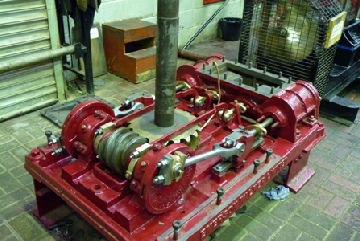
The two cylinder steam pump (built by John Cameron, Manchester), was given a trial steaming, on Wed 27th Nov 2013, after being stripped down and rebuilt. The steaming revealed excess lateral movement of the crank pin.
On closer examination one end of the crankshaft was found to be bent by about 1/8 of an inch, and as the crankshaft overhangs the main bearing by only 3 inches, a very large force must have caused it to bend.
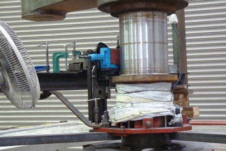
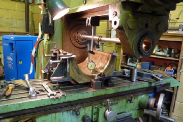
Straightening the shaft was out of the question, so it was decided to try and machine the shaft back to a true diameter. Due to its shape, it was not possible to set it up in our lathe. A jig, to hold and traverse a cutting tool, was designed and fitted to the frame of the pump.
The cutting process was carried out by carefully rotating the shaft by hand i.e. pulling on the flywheel, (an arm aching job).
Once a cut had been applied, the tool was traversed along by slowly turning a screw thread. The first pass was successful and after one or two slight adjustments the end of the shaft was eventually machined round and true.
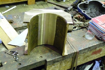
Since the shaft was now under size, a split sleeve was made so that the crank could be refitted and keyed to the crankshaft.
Museum News 2014
Updated December 2014

March 2014
Clapham Beam Engine -
The long and painstaking process of grinding the crankshaft journal has continued. Most of the badly pitted and corroded surface has been ground back to a good surface, but has left a grooved finish.
The bench grinder setup was reinstalled to remove the peaks of the grooves, but once again the grinder stalled at the smallest of cuts.
Some scratching of heads was employed, which resulted in trying the use of a small belt sander. Once this setup had been finalised the results were most encouraging.
The surface finish was now good enough to take accurate micrometer readings, which revealed that some adjustments had to be carried out to maintain a parallel diameter.
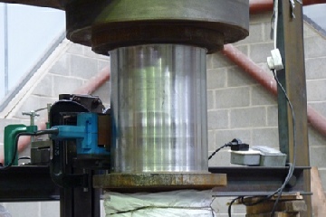
The belt sander setup in place giving a good surface finish.
The lower part of the journal shows the grooved finish.
Emerson Walker
Capstan Engine -
The eccentrics and associated rods and valves have been fitted. The valve timings and cylinder clearances have also been set.
The valve chest cover and reversing lever are now in place and cylinder covers bolted on. All glands have had new packing inserted.
The next stage will be to place the drum and support casting over the engine, which unfortunately, will cover up most of the engine and hide the nice bright metal and newly painted parts.
Eccentrics and associated rods and valves fitted.
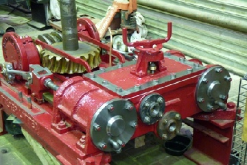
Valve chest cover fitted, showing reversing lever on top. Cylinder covers fitted.

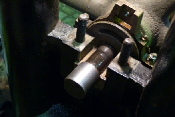
A round, single point, cutting tool taking a cut on the crankshaft. The screw thread, in view, controls the cross traverse.
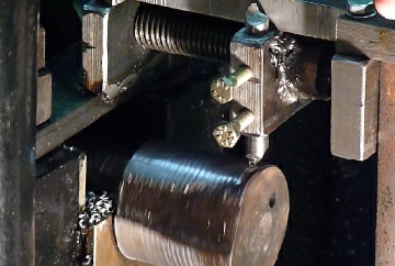
The crankshaft is now finished round and true.
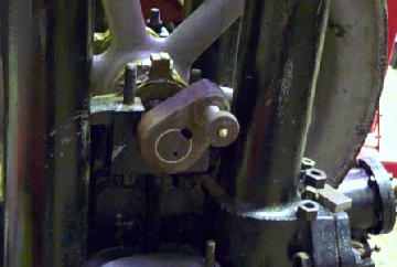
You can clearly see the crank and split bush in place, ready for the key to be fitted.

July 2014
Clapham Beam Engine -
The grinding of the crankshaft journal has now finished. The surface finish and parallel measurements are now satisfactory, and are as good as can achieved with the equipment and set up we have. The final diameter has been reduced from a nominal 10 ins. to 9.654 ins. Work on the bottom bearing brass will have to be carried out to accommodate this.
The bedplate has been moved, from the middle of the museum, to its intended place on the engine sub-
The finished journal, showing a good surface finish, compared with the original in the photo right.
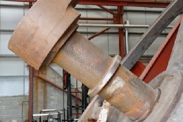
Original corroded journal
Emerson Walker Capstan Engine -
The final stage of fitting the capstan drum and support casting has been completed. The drains for the valve chest and cylinders have been connected to the exhaust pipework using copper tube and fittings. It is now ready for a trial steaming.
The completed capstan engine.
It's a shame, but most of the hard work is now covered up
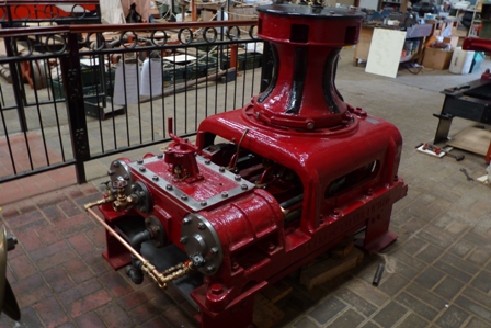
Donkin Steering Engine -
A trial steam took place on Wednesday 11th June 2014. Initially, some adjustments to the stops on the steering valve mechanism had to be made. After that it ran beautifully. Just the rudder to make and fit before it goes on display in the museum.
Cameron Pump -
The Joseph Evans 'banjo' steam pump has been removed for much needed repair work. The Cameron pump has been put in its place and will shortly be ready to be displayed and run in the museum.
October 2014
Clapham Beam Engine -
Now that the grinding of the crankshaft journal is near completion, attention has focused on the lower half of its brass bearing (The top half is missing, which adds to the list of other problems yet to be solved).
The bottom surface of this half brass will have to be machined to the new diameter of the crankshaft. This will have the effect of reducing the thickness, and weakening, the lower part of the brass. To keep this to a minimum the depth to which the new diameter can be machined will be limited, which will have the effect of reducing the contact area of the crankshaft in the bearing.
The machining is to be carried out on our large milling machine. A fabricated jig has been made to securely hold the half brass, in a way, that no distortion takes place when it is clamped to the machine bed.
Emerson Walker Capstan Engine -
On Wednesday 20th August 2014 the capstan engine was steamed for the first time since its arrival at the museum in Jan 2012.
Apart from a few niggling leaks the engine ran very well in both forward and reverse directions. As with one or two other restored exhibits, it will only be a static display until space becomes available, which will happen when the rebuilding the Clapham Beam Engine starts to take shape.
Cameron Steam Pump -
When this pump was connected to the steam supply and run, the pump did not perform very well. Upon investigation it was found that one of the delivery passages, close to a delivery valve, was completely blocked with rust and sediment. This has been cleared and the pump now works quite well.
Joseph Evans Steam Pump -
The pump has been completely stripped down ready for detailed inspection. Initial findings have uncovered a fractured casting, which is part of the big end bearing assembly. It looks as though this is an old breakage , which has been braze welded in an, unsuccessful, attempt to repair it. It is intended to machine a complete new part from a solid piece of steel, which should ensure a permanent solution.
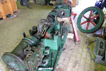
The Joseph Evans steam pump, partly stripped down.
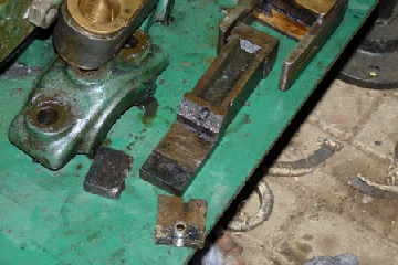
The broken cast component, on the Joseph Evans steam pump. Evidence of a previously brazed repair can be seen (next to the grub screw).
November 2014
Clapham Beam Engine -
To avoid any more stress on the cracked bedplate, it was decided to fit jacking screws to the bedplate, close to the holding down bolt holes. The jacking screws will provide an accurate adjustment to support the the bedplate before finally bolting it down.
The next task was to start machining the original bottom brass to the new diameter of the crankshaft. We couldn't machine to the full diameter -
Before machining could be started a jig was made to fully support and hold the brass, without any distortion taking place, whilst clamping to the milling machine table.
To get an accurately machined diameter, using the milling machine, a flycutter was made with a means of adjusting the single point cutter to the diameter required.
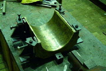
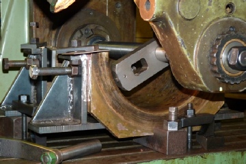
The original bottom brass fitted to the machining jig.
Setting up in the milling machine.
Machining completed, showing 5 ins. of contact area on bottom of the brass.
The flycutter mounted on the milling machine arbor prior to machining.