| Museum News 2013 |
|
(Back to Archive News Page) |
|
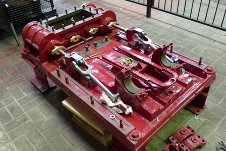
April 2013 Capstan Engine Update This engine has been completely dismantled and cleaned up, ready for assembly. The bedplate has been painted a burgundy colour (not its original colour) it was black when we received it.
|
| Newly painted capstan engine bedplate with cross-heads and connecting rods fitted. |
|
|
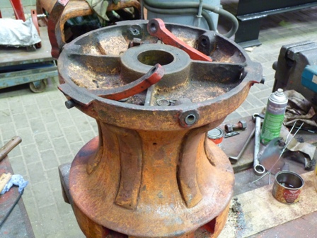
Capstan drum turned upside down, to gain access to the ratchet pins. In this photo you can see the offending pins sticking out on the left and right of the drum. The central pin has been cut off flush and drilled. The remaining part of the pin was cut through with a hacksaw to aid removal. |
|
Beam Engine update The on going dilemma of how to overcome the problem of the badly corroded crakshaft main bearing journal (bearing surface), has been resolved. To get an outside contractor in to re-machine the surface, was far too expensive for us, so it was decided to attempt to grind it ourselves by designing and making a steel framework, which will rotate about the same axis as the crankshaft, while it is in its present postion (i.e. flywheel horizontal and shaft vertical). The framework is to carry a grinding head that can be moved inwards towards the journal surface and also traverse along its axis. Two slideways at 90 degrees to each other will achieve this. The top of the framework is attached to a rotating hub which rests on the top of the crank. the lower part is supported by a split brass bearing to rotate around a good part of the crankshaft. The following photos will probably explain this better.
|
|
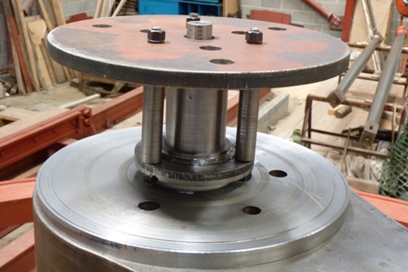
This photo shows the fabricated hub on top of the crank. The bottom thick flange is stationary and is recessed to centralise it on the projecting crankshaft. The upper flange etc. rotates on a short, vertical shaft, with two sealed ball bearings. A ball thrust bearing supports the weight of the whole structure.
The large diameter holes in the top flange are used to fasten the top of the framework. |
|
|
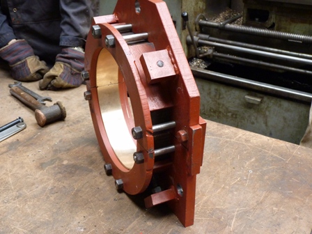
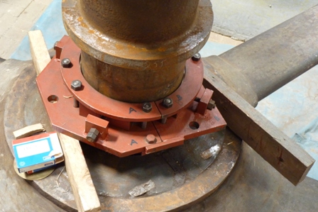
This shows the assembled bottom brass bearing, made to split into two halves to fit over the crankshaft.
The half brasses have been subdivided into quarters. |
|
This shows the bottom split bearing in place, just above the flywheel hub.
The adjusters in view are used to push the brass segments onto the shaft. |
|
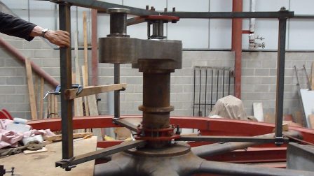
| This shows part of the framework in place and how the top hub and bottom bearing are assembled on the crankshaft. This ensures that the structure, which will carry the grinding head, rotates about the same axis as the crankshaft. |
|
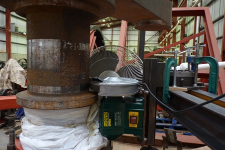
October 2013 Clapham Beam Engine A bench grinding machine with 8ins. wheel has been mounted onto the rotating framework and the first attempt to grind the badly corroded bearing journal was very encouraging. In principle the setup works quite well, but in practice the grinding head stalls very easily when applying even the smallest of cuts.
Once all the corroded surface has been removed down to clean metal, the bench grinder setup will be used again, to try and produce a suitable surface finish.
|
| First attempt at grinding the bearing journal, using a bench grinding machine. |
|
|
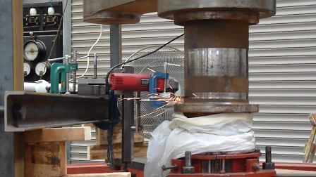
Small angle grinder replaced the bench grinder.
The wheel guard and spark collector have been temporarily removed to make a clearer photo. |